|
|||||||||||||||
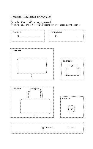
One of the main reasons for utilizing a computer design systems is for the use, and re-use, of repetitive elements in your drawings. A symbol is simply a group of drawing elements, such as lines, arcs and circles, which represent an object, such as a door or chair. Once you have saved these elements into a symbol and placed it into your drawing, all of its parts will be treated as a single entity. Symbol/Make allows you to create these elements one time and then Symbol Place them over and over. You can scale and rotate symbols as you place them. There are many advantages to using symbols and these include global replacements, symbol counts and database attributes. These symbols should have logical names so that they are easily recognized, and they should be organized into directories (or libraries) that reflect certain types of symbols (i.e. doors and windows, plumbing, electrical equipment, etc.). Once you have created a symbol from elements such as lines and arcs, it will no longer be associated to those basic elements. Symbol creation requires a basepoint (or handle), and that specific location will be used as the reference point for placement of the symbol. To edit a symbol in any way, you must expand it back to its original drawing elements, but then of course, you can no longer take advantage of the tools mentioned in the last paragraph! Remember that when you expand a symbol or group, Top means that if several objects have been placed together to form the symbol or group, they will be dis-associated from one another, but still retain their separate symbol identities. Whereas, utilizing the All command will completely expand the objects back to their original drawing elements. A symbol is limited in size to 255 individual drawing elements, and as such is a relatively uncomplicated object (complex details are usually too large to be symbols and must be saved as drawing files). Symbol Groups are similar to symbols in that one or more drawing elements are combined to create a single entity. These can include symbols and drawing entities like text or lines, and makes it much easier to associate a group of objects for duplication or rotation or whatever. Unlike symbols, these groups are not separate files that can be utilized by several drawings, but rather are combined for use only in the current drawing file. Like symbols though, if you select any object in the group, the entire group will be highlighted for manipulation and will remain grouped together in the file until you Expand the Group. Symbol Creation Exercise: Please go to the following pages and create the symbols as defined. Be sure to utilize a grid when creating symbols, so that each will be created accurately.
|
|||||||||||||||
Note that textures must be created in a specific order. Symbol first (with a node reference point). then a Line Texture, then an Area Texture. Although textures can improve the look of a design, they tend to reproduce slowly because of the many symbols involved. Texture Creation Exercise: Following the detail below, create a symbol called "ZIG" (don't forget the node). Create a Line Texture from it called "ZAG". Now create an Area Texture called "ZIGZAG". Draw a rectangle and fill it with the Area Texture, and try the Line Texture also (Notice what happens to the ends on line textures. Can you explain why?).
CHAIR16.SYM w Set GRID/SIZE =
1" x 1". w Set Snap to GRID (.G). w Goto DRAW/FILLET (Alt DF). w Goto SYMBOL/MAKE (Alt SM). w Set PATH = Samples Directory. WINWALL.SYM w Goto DRAW/LINE
(Alt DL) w Draw the line between 2 grid points. Total length =
1". w Goto SYMBOL/MAKE. w Set BASEPOINT as indicated on end of line opposite
node.
You can now place the symbol (Alt S P), and remember to
scale it up to the appropriate size (i.e. 36 would = a 3' window wall). DESK42.SYM w Goto
DRAW/RECTANGLE (Alt DR). w Set PATH = Samples Directory. PLANT.SYM w The plant can be
drawn in a variety of ways. OFFICE1.SYM OFFICE1 is merely a combined symbol with CHAIR16 and DESK42 "nested" within. Place the two symbols and then goto SYMBOL/MAKE and save them as OFFICE1 with the same basepoint as DESK42. OPENWALL.SYM This is created just like WINWALL.SYM. The node is the symbol, and the basepoint is 1" to the right. As with WINWALL, you can now place the symbol (Alt S P), and remember to scale it up to the appropriate wall opening size (i.e. 60 would = a 5' wall opening). Normally when you place wall openings, you will use the EDIT/ALTER/OPEN SEGMENT command and be sure to set in the appropriate wall gap. Also be sure to change to your wall placement layer to the correct layer, prior to inserting it.
|
|||||||||||||||
|
End of Lesson 3 - Next Lesson >>>
|
|||||||||||||||
Home | Products | News | Technical | Forum | Gallery | Downloads | Links | About FIT


